- Home
- Businesses
-
-
-
Industrial NanoTech Businesses
-
What’s New
Many pandemic-driven changes to cancer clinical trials should remain
Lorem Ipsum is simply dummy text of the printing and typesetting industry. Lorem Ipsum has been…
Immunotherapy May Be Effective for Subset of Patients With Prostate Cancer
Lorem Ipsum is simply dummy text of the printing and typesetting industry. Lorem Ipsum has been…
Gap in Breast Cancer Survival for Black, White Patients Shrinks, But Not by Enough
Lorem Ipsum is simply dummy text of the printing and typesetting industry. Lorem Ipsum has been…
-
-
-
-
-
- Brands
-
-
-
Industrial NanoTech Brands
-
What’s New
Many pandemic-driven changes to cancer clinical trials should remain
Lorem Ipsum is simply dummy text of the printing and typesetting industry. Lorem Ipsum has been…
Immunotherapy May Be Effective for Subset of Patients With Prostate Cancer
Lorem Ipsum is simply dummy text of the printing and typesetting industry. Lorem Ipsum has been…
Gap in Breast Cancer Survival for Black, White Patients Shrinks, But Not by Enough
Lorem Ipsum is simply dummy text of the printing and typesetting industry. Lorem Ipsum has been…
-
-
-
-
- Research & Innovation
-
-
-
Industrial NanoTech Research & Innovation
-
What’s New
Many pandemic-driven changes to cancer clinical trials should remain
Lorem Ipsum is simply dummy text of the printing and typesetting industry. Lorem Ipsum has been…
Immunotherapy May Be Effective for Subset of Patients With Prostate Cancer
Lorem Ipsum is simply dummy text of the printing and typesetting industry. Lorem Ipsum has been…
Gap in Breast Cancer Survival for Black, White Patients Shrinks, But Not by Enough
Lorem Ipsum is simply dummy text of the printing and typesetting industry. Lorem Ipsum has been…
-
-
-
- Self Reporting TechnologiesLorem ipsum is a placeholder text commonly used to demonstrate the visual form of a document or a typeface without relying on meaningful content.
- Advanced Thermal InsulationLorem ipsum is a placeholder text commonly used to demonstrate the visual form of a document or a typeface without relying on meaningful content.
- Corrosion Prevention TechnologiesLorem ipsum is a placeholder text commonly used to demonstrate the visual form of a document or a typeface without relying on meaningful content.
- Clean Energy GenerationLorem ipsum is a placeholder text commonly used to demonstrate the visual form of a document or a typeface without relying on meaningful content.
- Workplace SafetyLorem ipsum is a placeholder text commonly used to demonstrate the visual form of a document or a typeface without relying on meaningful content.
- Nurturing ScientistsLorem ipsum is a placeholder text commonly used to demonstrate the visual form of a document or a typeface without relying on meaningful content.
-
-
-
- Industries
-
-
-
Industrial NanoTech Industries
-
What’s New
Many pandemic-driven changes to cancer clinical trials should remain
Lorem Ipsum is simply dummy text of the printing and typesetting industry. Lorem Ipsum has been…
Immunotherapy May Be Effective for Subset of Patients With Prostate Cancer
Lorem Ipsum is simply dummy text of the printing and typesetting industry. Lorem Ipsum has been…
Gap in Breast Cancer Survival for Black, White Patients Shrinks, But Not by Enough
Lorem Ipsum is simply dummy text of the printing and typesetting industry. Lorem Ipsum has been…
-
-
-
-
- Careers
-
-
-
Industrial NanoTech Careers
-
What’s New
Many pandemic-driven changes to cancer clinical trials should remain
Lorem Ipsum is simply dummy text of the printing and typesetting industry. Lorem Ipsum has been…
Immunotherapy May Be Effective for Subset of Patients With Prostate Cancer
Lorem Ipsum is simply dummy text of the printing and typesetting industry. Lorem Ipsum has been…
Gap in Breast Cancer Survival for Black, White Patients Shrinks, But Not by Enough
Lorem Ipsum is simply dummy text of the printing and typesetting industry. Lorem Ipsum has been…
-
-
-
- JobsLorem ipsum is a placeholder text commonly used to demonstrate the visual form of a document or a typeface without relying on meaningful content.
- Benefits & RewardsLorem ipsum is a placeholder text commonly used to demonstrate the visual form of a document or a typeface without relying on meaningful content.
- Life At Industrial NanotechLorem ipsum is a placeholder text commonly used to demonstrate the visual form of a document or a typeface without relying on meaningful content.
- How We HireLorem ipsum is a placeholder text commonly used to demonstrate the visual form of a document or a typeface without relying on meaningful content.
- StudentsLorem ipsum is a placeholder text commonly used to demonstrate the visual form of a document or a typeface without relying on meaningful content.
-
-
-
- Newsroom
-
-
-
Industrial NanoTech Newsroom
-
What’s New
Many pandemic-driven changes to cancer clinical trials should remain
Lorem Ipsum is simply dummy text of the printing and typesetting industry. Lorem Ipsum has been…
Immunotherapy May Be Effective for Subset of Patients With Prostate Cancer
Lorem Ipsum is simply dummy text of the printing and typesetting industry. Lorem Ipsum has been…
Gap in Breast Cancer Survival for Black, White Patients Shrinks, But Not by Enough
Lorem Ipsum is simply dummy text of the printing and typesetting industry. Lorem Ipsum has been…
-
-
-
- NewsroomLorem ipsum is a placeholder text commonly used to demonstrate the visual form of a document or a typeface without relying on meaningful content.
- Media ContactsLorem ipsum is a placeholder text commonly used to demonstrate the visual form of a document or a typeface without relying on meaningful content.
- Media CoverageLorem ipsum is a placeholder text commonly used to demonstrate the visual form of a document or a typeface without relying on meaningful content.
- Social MediaLorem ipsum is a placeholder text commonly used to demonstrate the visual form of a document or a typeface without relying on meaningful content.
- VideosLorem ipsum is a placeholder text commonly used to demonstrate the visual form of a document or a typeface without relying on meaningful content.
-
-
-
- Investor Relations
-
-
-
Industrial NanoTech Investor Relations
-
What’s New
Many pandemic-driven changes to cancer clinical trials should remain
Lorem Ipsum is simply dummy text of the printing and typesetting industry. Lorem Ipsum has been…
Immunotherapy May Be Effective for Subset of Patients With Prostate Cancer
Lorem Ipsum is simply dummy text of the printing and typesetting industry. Lorem Ipsum has been…
Gap in Breast Cancer Survival for Black, White Patients Shrinks, But Not by Enough
Lorem Ipsum is simply dummy text of the printing and typesetting industry. Lorem Ipsum has been…
-
-
-
- Investor RelationsLorem ipsum is a placeholder text commonly used to demonstrate the visual form of a document or a typeface without relying on meaningful content.
- NewsLorem ipsum is a placeholder text commonly used to demonstrate the visual form of a document or a typeface without relying on meaningful content.
- Events and presentationsLorem ipsum is a placeholder text commonly used to demonstrate the visual form of a document or a typeface without relying on meaningful content.
- Stock InformationLorem ipsum is a placeholder text commonly used to demonstrate the visual form of a document or a typeface without relying on meaningful content.
- SEC FilingsLorem ipsum is a placeholder text commonly used to demonstrate the visual form of a document or a typeface without relying on meaningful content.
- GovernanceLorem ipsum is a placeholder text commonly used to demonstrate the visual form of a document or a typeface without relying on meaningful content.
-
-
-
- Our Company
-
-
-
Industrial NanoTech Our Company
-
What’s New
Many pandemic-driven changes to cancer clinical trials should remain
Lorem Ipsum is simply dummy text of the printing and typesetting industry. Lorem Ipsum has been…
Immunotherapy May Be Effective for Subset of Patients With Prostate Cancer
Lorem Ipsum is simply dummy text of the printing and typesetting industry. Lorem Ipsum has been…
Gap in Breast Cancer Survival for Black, White Patients Shrinks, But Not by Enough
Lorem Ipsum is simply dummy text of the printing and typesetting industry. Lorem Ipsum has been…
-
-
-
- Company HistoryLorem ipsum is a placeholder text commonly used to demonstrate the visual form of a document or a typeface without relying on meaningful content.
- Leadership TeamLorem ipsum is a placeholder text commonly used to demonstrate the visual form of a document or a typeface without relying on meaningful content.
- What We Stand ForLorem ipsum is a placeholder text commonly used to demonstrate the visual form of a document or a typeface without relying on meaningful content.
- Quality PolicyLorem ipsum is a placeholder text commonly used to demonstrate the visual form of a document or a typeface without relying on meaningful content.
- Community ManagementLorem ipsum is a placeholder text commonly used to demonstrate the visual form of a document or a typeface without relying on meaningful content.
- Awards & RecognitionLorem ipsum is a placeholder text commonly used to demonstrate the visual form of a document or a typeface without relying on meaningful content.
-
-
-
- Contact Us
-
-
-
Industrial NanoTech Contact Us
-
-
-
-
- Headquarter locationLorem ipsum is a placeholder text commonly used to demonstrate the visual form of a document or a typeface without relying on meaningful content.
- Job searchLorem ipsum is a placeholder text commonly used to demonstrate the visual form of a document or a typeface without relying on meaningful content.
- Submit RFPLorem ipsum is a placeholder text commonly used to demonstrate the visual form of a document or a typeface without relying on meaningful content.
-
-
-
- Become a Distributor
Industrial NanoTech
Navigation
- Home
- Businesses
-
-
-
Industrial NanoTech Businesses
-
What’s New
Many pandemic-driven changes to cancer clinical trials should remain
Lorem Ipsum is simply dummy text of the printing and typesetting industry. Lorem Ipsum has been…
Immunotherapy May Be Effective for Subset of Patients With Prostate Cancer
Lorem Ipsum is simply dummy text of the printing and typesetting industry. Lorem Ipsum has been…
Gap in Breast Cancer Survival for Black, White Patients Shrinks, But Not by Enough
Lorem Ipsum is simply dummy text of the printing and typesetting industry. Lorem Ipsum has been…
-
-
-
-
-
- Brands
-
-
-
Industrial NanoTech Brands
-
What’s New
Many pandemic-driven changes to cancer clinical trials should remain
Lorem Ipsum is simply dummy text of the printing and typesetting industry. Lorem Ipsum has been…
Immunotherapy May Be Effective for Subset of Patients With Prostate Cancer
Lorem Ipsum is simply dummy text of the printing and typesetting industry. Lorem Ipsum has been…
Gap in Breast Cancer Survival for Black, White Patients Shrinks, But Not by Enough
Lorem Ipsum is simply dummy text of the printing and typesetting industry. Lorem Ipsum has been…
-
-
-
-
- Research & Innovation
-
-
-
Industrial NanoTech Research & Innovation
-
What’s New
Many pandemic-driven changes to cancer clinical trials should remain
Lorem Ipsum is simply dummy text of the printing and typesetting industry. Lorem Ipsum has been…
Immunotherapy May Be Effective for Subset of Patients With Prostate Cancer
Lorem Ipsum is simply dummy text of the printing and typesetting industry. Lorem Ipsum has been…
Gap in Breast Cancer Survival for Black, White Patients Shrinks, But Not by Enough
Lorem Ipsum is simply dummy text of the printing and typesetting industry. Lorem Ipsum has been…
-
-
-
- Self Reporting TechnologiesLorem ipsum is a placeholder text commonly used to demonstrate the visual form of a document or a typeface without relying on meaningful content.
- Advanced Thermal InsulationLorem ipsum is a placeholder text commonly used to demonstrate the visual form of a document or a typeface without relying on meaningful content.
- Corrosion Prevention TechnologiesLorem ipsum is a placeholder text commonly used to demonstrate the visual form of a document or a typeface without relying on meaningful content.
- Clean Energy GenerationLorem ipsum is a placeholder text commonly used to demonstrate the visual form of a document or a typeface without relying on meaningful content.
- Workplace SafetyLorem ipsum is a placeholder text commonly used to demonstrate the visual form of a document or a typeface without relying on meaningful content.
- Nurturing ScientistsLorem ipsum is a placeholder text commonly used to demonstrate the visual form of a document or a typeface without relying on meaningful content.
-
-
-
- Industries
-
-
-
Industrial NanoTech Industries
-
What’s New
Many pandemic-driven changes to cancer clinical trials should remain
Lorem Ipsum is simply dummy text of the printing and typesetting industry. Lorem Ipsum has been…
Immunotherapy May Be Effective for Subset of Patients With Prostate Cancer
Lorem Ipsum is simply dummy text of the printing and typesetting industry. Lorem Ipsum has been…
Gap in Breast Cancer Survival for Black, White Patients Shrinks, But Not by Enough
Lorem Ipsum is simply dummy text of the printing and typesetting industry. Lorem Ipsum has been…
-
-
-
-
- Careers
-
-
-
Industrial NanoTech Careers
-
What’s New
Many pandemic-driven changes to cancer clinical trials should remain
Lorem Ipsum is simply dummy text of the printing and typesetting industry. Lorem Ipsum has been…
Immunotherapy May Be Effective for Subset of Patients With Prostate Cancer
Lorem Ipsum is simply dummy text of the printing and typesetting industry. Lorem Ipsum has been…
Gap in Breast Cancer Survival for Black, White Patients Shrinks, But Not by Enough
Lorem Ipsum is simply dummy text of the printing and typesetting industry. Lorem Ipsum has been…
-
-
-
- JobsLorem ipsum is a placeholder text commonly used to demonstrate the visual form of a document or a typeface without relying on meaningful content.
- Benefits & RewardsLorem ipsum is a placeholder text commonly used to demonstrate the visual form of a document or a typeface without relying on meaningful content.
- Life At Industrial NanotechLorem ipsum is a placeholder text commonly used to demonstrate the visual form of a document or a typeface without relying on meaningful content.
- How We HireLorem ipsum is a placeholder text commonly used to demonstrate the visual form of a document or a typeface without relying on meaningful content.
- StudentsLorem ipsum is a placeholder text commonly used to demonstrate the visual form of a document or a typeface without relying on meaningful content.
-
-
-
- Newsroom
-
-
-
Industrial NanoTech Newsroom
-
What’s New
Many pandemic-driven changes to cancer clinical trials should remain
Lorem Ipsum is simply dummy text of the printing and typesetting industry. Lorem Ipsum has been…
Immunotherapy May Be Effective for Subset of Patients With Prostate Cancer
Lorem Ipsum is simply dummy text of the printing and typesetting industry. Lorem Ipsum has been…
Gap in Breast Cancer Survival for Black, White Patients Shrinks, But Not by Enough
Lorem Ipsum is simply dummy text of the printing and typesetting industry. Lorem Ipsum has been…
-
-
-
- NewsroomLorem ipsum is a placeholder text commonly used to demonstrate the visual form of a document or a typeface without relying on meaningful content.
- Media ContactsLorem ipsum is a placeholder text commonly used to demonstrate the visual form of a document or a typeface without relying on meaningful content.
- Media CoverageLorem ipsum is a placeholder text commonly used to demonstrate the visual form of a document or a typeface without relying on meaningful content.
- Social MediaLorem ipsum is a placeholder text commonly used to demonstrate the visual form of a document or a typeface without relying on meaningful content.
- VideosLorem ipsum is a placeholder text commonly used to demonstrate the visual form of a document or a typeface without relying on meaningful content.
-
-
-
- Investor Relations
-
-
-
Industrial NanoTech Investor Relations
-
What’s New
Many pandemic-driven changes to cancer clinical trials should remain
Lorem Ipsum is simply dummy text of the printing and typesetting industry. Lorem Ipsum has been…
Immunotherapy May Be Effective for Subset of Patients With Prostate Cancer
Lorem Ipsum is simply dummy text of the printing and typesetting industry. Lorem Ipsum has been…
Gap in Breast Cancer Survival for Black, White Patients Shrinks, But Not by Enough
Lorem Ipsum is simply dummy text of the printing and typesetting industry. Lorem Ipsum has been…
-
-
-
- Investor RelationsLorem ipsum is a placeholder text commonly used to demonstrate the visual form of a document or a typeface without relying on meaningful content.
- NewsLorem ipsum is a placeholder text commonly used to demonstrate the visual form of a document or a typeface without relying on meaningful content.
- Events and presentationsLorem ipsum is a placeholder text commonly used to demonstrate the visual form of a document or a typeface without relying on meaningful content.
- Stock InformationLorem ipsum is a placeholder text commonly used to demonstrate the visual form of a document or a typeface without relying on meaningful content.
- SEC FilingsLorem ipsum is a placeholder text commonly used to demonstrate the visual form of a document or a typeface without relying on meaningful content.
- GovernanceLorem ipsum is a placeholder text commonly used to demonstrate the visual form of a document or a typeface without relying on meaningful content.
-
-
-
- Our Company
-
-
-
Industrial NanoTech Our Company
-
What’s New
Many pandemic-driven changes to cancer clinical trials should remain
Lorem Ipsum is simply dummy text of the printing and typesetting industry. Lorem Ipsum has been…
Immunotherapy May Be Effective for Subset of Patients With Prostate Cancer
Lorem Ipsum is simply dummy text of the printing and typesetting industry. Lorem Ipsum has been…
Gap in Breast Cancer Survival for Black, White Patients Shrinks, But Not by Enough
Lorem Ipsum is simply dummy text of the printing and typesetting industry. Lorem Ipsum has been…
-
-
-
- Company HistoryLorem ipsum is a placeholder text commonly used to demonstrate the visual form of a document or a typeface without relying on meaningful content.
- Leadership TeamLorem ipsum is a placeholder text commonly used to demonstrate the visual form of a document or a typeface without relying on meaningful content.
- What We Stand ForLorem ipsum is a placeholder text commonly used to demonstrate the visual form of a document or a typeface without relying on meaningful content.
- Quality PolicyLorem ipsum is a placeholder text commonly used to demonstrate the visual form of a document or a typeface without relying on meaningful content.
- Community ManagementLorem ipsum is a placeholder text commonly used to demonstrate the visual form of a document or a typeface without relying on meaningful content.
- Awards & RecognitionLorem ipsum is a placeholder text commonly used to demonstrate the visual form of a document or a typeface without relying on meaningful content.
-
-
-
- Contact Us
-
-
-
Industrial NanoTech Contact Us
-
-
-
-
- Headquarter locationLorem ipsum is a placeholder text commonly used to demonstrate the visual form of a document or a typeface without relying on meaningful content.
- Job searchLorem ipsum is a placeholder text commonly used to demonstrate the visual form of a document or a typeface without relying on meaningful content.
- Submit RFPLorem ipsum is a placeholder text commonly used to demonstrate the visual form of a document or a typeface without relying on meaningful content.
-
-
-
- Become a Distributor
Industrial NanoTech
Search
Frequently Asked Questions
Industrial NanoTech
Contacts
Address
Naples, FL 34109
Industrial NanoTech
<span data-metadata="“><span data-buffer="“>Social Network
Business
Corrosion Under Insulation(CUI) Mitigation
CUI: An In-Depth Analysis
Corrosion under insulation (CUI) is a well-understood problem, and mitigation methods are well established. However, it is pervasive and continues to cost the process industry many millions of dollars annually. In 2002 a large chemical company spent over $5 million dollars replacing 304 stainless steel equipment because of chloride stress corrosion cracking (CSCC) under insulation.1 The cost of the downtime due to the loss of production was even more significant. In another example, one petrochemical company estimates that CUI accounts for as high as 40 to 60 percent of the company’s piping maintenance costs.2 Similar case histories are commonplace within the process industries. An effective CUI prevention strategy based on life-cycle costs can significantly reduce costs due to downtime, maintenance repair, and inspection. The corrosion of carbon steel under wet insulation is nonuniform general corrosion and/or highly localized pitting. In austenitic stainless steels, the main forms of corrosion are pitting and stress corrosion cracking caused by chlorides.
Corrosion of Steel Under Insulation Mechanism
Figure 1 shows a section of a large carbon-steel storage that has undergone corrosion in a localized region leading to a through-wall hole. The corrosion occurred on the sidewall near the tank bottom where the coating failed, exposing the carbon steel to wet corrosive conditions under the insulation. Carbon steel does not corrode simply because it is covered with insulation, but because it is contacted by aerated water.
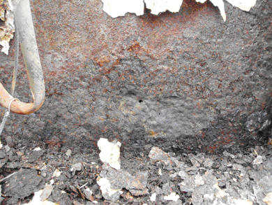
In a corroded system, insulation can provide an annular space or crevice for the retention of water with full access to oxygen (air) and other corrosive media. If not careful, the insulation can provide a material that may wick or absorb and may contribute contaminants that increase or accelerate the corrosion rate. The corrosion rate of carbon steel is principally controlled by the temperature of the steel surface, availability of oxygen and water, and the presence of corrosive contaminant species in the water.
Water sources. There are two primary water sources involved in CUI of carbon steel. First, breaks in the weatherproofing can lead to infiltration of water to the metal surface from external sources such as rainfall, drift from cooling towers, condensate falling from cold service equipment, steam discharge, process liquid spillage, spray from fire sprinklers, deluge systems, washrooms, and from condensation on cold surfaces after vapor-barrier damage. Second, a major corrosion problem develops in situations where there are cycling temperatures that vary from below the dew point to above-ambient temperatures. In this case, the classic wet/dry cycle occurs when the cold metal develops water condensation that is then baked off during the hot/dry cycle. The transition from cold/wet to hot/dry includes an interim period of damp/warm conditions with attendant high corrosion rates.
Contaminants. Chlorides and sulfates are the principal contaminants found under insulation. These may be leached from the insulation materials or from external waterborne or airborne sources. Chlorides and sulfates are particularly detrimental because their respective metal salts are highly soluble in water, and these aqueous solutions have high electrical conductivity. Furthermore, hydrolysis of the metal salts can create acidic conditions leading to localized corrosion.
Temperature. It is generally accepted that carbon steel operating in the temperature range of -4°C (25°F) to 149°C (300°F) is at the greatest risk from CUI. Equipment that operates continuously below -4°C (25°F) usually remains free of corrosion. Corrosion of equipment above 149°C (300°F), above the boiling point of water, is reduced because the carbon-steel surface remains essentially dry. Corrosion tends to occur at those points of water entry into the insulation system where the temperature is below 149°C (300°F) and when the equipment is idle. Figure 2 shows the corrosiveness of Insulation.

CUI of carbon steel is possible under all types of insulation. The rate of corrosion may vary depending on the characteristics of the insulation material. Some insulation materials contain water-leachable salts that may contribute to corrosion, and some foams may contain residual compounds that react with water to form an acidic environment. The water retention, permeability, and wettability properties of the insulation material also influence the corrosion of carbon steel.
corrosion under insulation can be classified as equivalent to corrosion in a closed hot-water system. In an open system, the oxygen content decreases with increasing temperature to the point where corrosion decreases even though the temperature continues to increase.3 In a closed system, the corrosion rate of carbon steel in water continues to increase as the water temperature increases. Estimated corrosion rate data of carbon steel under insulation plotted in Figure 2 that were obtained from actual plant case histories confirm that the rate increases with temperature in a manner similar to that of a closed system.4 It is inferred that the same oxygen cell corrosion mechanism is taking place as in a closed system. The corrosion rates from field measurements are shown to be greater than laboratory tests, due to the presence of salts in the field. Salts increase the conductivity of the water film and thereby influence the corrosion rate.
Corrosion of Stainless Steel Under Insulation
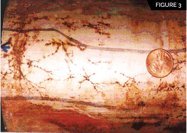
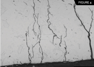
CUI in austenitic stainless steel is manifested by chloride-induced stress corrosion cracking (CISCC), commonly referred to as external stress corrosion cracking (ESCC) because the source of chlorides is external to the process environment. Figure 3 shows ESCC of a 4-inch 304 stainless steel pipe that operated in the 50°-to-100°C range. Figure 4 shows the typical transgranular lightning-strike appearance of ESCC in the pipe. ESCC of austenitic stainless steel is possible when the equipment is contacted by aerated water, chlorides, or contaminants in the temperature range of 50° to 150°C in the presence of tensile stresses.
The Mechanism
A detailed discussion on the mechanism of stress corrosion cracking (SCC) can be found in a number of publications.(5, 6) The mode of cracking is normally transgranular. It is well established that the propensity for ESCC is greatest when the following conditions are present:
- A susceptible 300 series austenitic stainless steel
- The presence of residual or applied surface tensile stresses
- The presence of chlorides, bromide, and fluoride ions may also be involved
- Metal temperature in the range 50° to 150°C
- The presence of an electrolyte (water)
Alloys. The stainless steels that are commonly affected by ESCC in the chemical process industries are the 300 series stainless steels, 304 type (UNS S30400 and S30403), 316 type (UNS S31600 and S31603), 317L (UNS S31700), 321 (UNS S32100), and 347 (UNS S34700). It should be noted that other stainless steels could also undergo ESCC under specific corrosive conditions.
Role of stress. For ESCC to develop, sufficient tensile stress must be present in the material. If the tensile stress is eliminated or greatly reduced, cracking will not occur. The threshold stress required to develop cracking depends somewhat on the severity of the cracking medium. Most mill products, such as sheet, plate, pipe, and tubing, contain enough residual tensile stresses from processing to develop cracks without external stresses. When the austenitic stainless steels are cold formed and welded, additional stresses are imposed. The incidence of ESCC is greater in process piping because of the high hop stresses normally present in piping systems. As the total stress increases, the potential for ESCC increases.
Chlorides. Chloride ion is damaging to the passive protective layer on 18-8 stainless steels. Once the passive layer is penetrated, localized corrosion cells become active. Under the proper set of circumstances, SCC can lead to failure in only a few days or weeks. Sodium chloride, because of its high solubility and widespread presence, is the most common corrosive species.5 This neutral salt is the most common, but not the most aggressive. Chloride salts of the weak bases and light metals, such as lithium chloride, magnesium chloride, and aluminium chloride, can even more rapidly crack the 18-8 stainless steels under the right conditions of temperature and moisture content. The sources of chlorides in ESCC are from insulating materials and external sources. The insulating materials include insulation, mastics, sealants, adhesives, and cements. Experience has shown that insulating materials with chloride content as little as 350 parts per million (ppm) can contribute to ESCC. Typically, if the insulating material is the source of leachable chlorides, failure occurs only after a few years of operation. However, external sources of chloride account for most of the ESCC failures. The sources include rain, coastal fog, wash water, fire- and deluge-system testing, and process leaks or spills. Other sources of chloride ions known to be aggressive include chlorine, hydrogen chloride gas, hydrochloric acid, and hydrolyzed organic chlorides. Clearly, the presence of chlorides under acidic conditions is more aggressive than neutral or basic conditions. Failures due to chlorides from external sources tend to occur after 5 or more years of service.
The concentration of chlorides necessary to initiate SCC is difficult to ascertain. Researchers have developed cracking in solutions with remarkably low levels of chlorides—less than 10 ppm. The situation of chlorides under insulation is unique and ultimately depends on the concentration of chlorides deposited on the external surface of the metal. Deposits near ESCC failures have been found with as little as 1,000 ppm chloride. If chlorides are detected, there will probably be some localized sites of high concentration.
Temperature. The most important condition affecting chloride concentration is the temperature of the metal surface. Temperature has a dual effect: 1) Elevated temperatures will cause water evaporation on the metal surface, which results in chloride concentration; and 2) as the temperature increases, the susceptibility to initiation and propagation of ESCC increases. ESCC occurs more frequently in the range 50° to 150°C. Below 50°C, chlorides do not concentrate to levels that cause ESCC. Above 150°C, water is not normally present on the metal surface, and failures are uncommon. Equipment that cycles through the water dew point is particularly susceptible because during each temperature cycle the chloride salts in the water concentrate on the surface.
Electrolyte. Water is the fourth necessary condition for ESCC. Since SCC involves an electrochemical reaction, it requires an electrolyte. As water penetrates the insulation system, it plays a key role at the metal surface, depending on the equipment operating conditions. Examination of the phenomenon of corrosion of steel under insulation provides a better appreciation of the widespread intrusion of water.7, 8, 9 In effect, water may be expected to enter the metal and insulation annulus at joints or breaks in the insulation and its protective coating. The water then condenses or wets the metal surface, or if it is too hot, the water is vaporized.7 This water vapor (steam) penetrates the entire insulation system and settles into places where it can recondense. Because the outer surface of the insulation is designed to keep water out, it also serves to keep water in. The thermal insulation does not have to be in poor condition or constantly water soaked. A common practice in chemical plants is to turn on the fire-protection water systems on a regular basis. This deluges the equipment with water. Some coastal locations use seawater for the fire-protection water. Hot food-processing equipment is regularly washed with tap water, which contains chlorides. All insulation-system water barriers eventually develop defects. As the vessel and insulation system breathes, moist air contacts the metal surface. From the insulation standpoint, the outer covering acts as a weather barrier to protect the physical integrity of the insulation material. The outer coverings are not intended, nor can they be expected, to maintain an airtight and watertight system.
Prevention of CUI
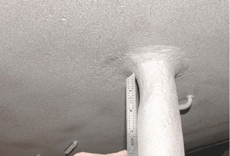
When designing an insulation system the goal is to prevent ingress of moisture. Poorly designed or applied insulation and protrusions through thermal insulation permit water to bypass the insulation, thereby corroding the substrate material. References 10 and 11 provide detailed information on the mechanical design of insulation systems. Attachments to vessels and piping stems are common locations that allow water to bypass the insulation and to concentrate at the attachment point. Examples of such attachments are shown in Figures 5 and 6. Attention to details such as these is important in order to produce a high-quality insulation system. Although the design of the insulation system is important, prevention methodologies based on design alone are not advisable or practical in a chemical plant. The physical characteristics of thermal insulation materials can vary widely. Some insulation materials contain a leachable inhibitor to neutralize the pH of the water in contact with the metal surface. The degree of water absorbency can also vary. For some systems, the coefficient of thermal expansion will influence the system design. For example, cellular glass insulation expands about the same as carbon steel, whereas cellular foam expands nine times more than carbon steel and therefore requires expansion joints. General industry experience over the last 20 years indicates that corrosion is possible under all types of insulation. The common types of insulation materials and their recommended service temperatures are listed in Table 1. Selecting and specifying the correct insulation material can reduce corrosion of both carbon and stainless steels.
Organic coating system. The application of organic coatings on both carbon and stainless steel equipment beneath insulation is an effective method of having a physical barrier to the corrosive electrolytes and thereby preventing corrosion. This method is effective only if a holiday-free coated surface is obtained. In the chemical plant environment, the average life cycle of a coating system is 5 to 13 years.12 In some cases, when a correctly selected and applied coating system is used, a 20-year service life can be achieved. Some of the parameters that need to be considered when selecting a coating system include: coating selection, surface-preparation requirements, environmental requirements, compatibility with insulating material, coating tests, coating vendor selection, specifications, inspection, and selection of a coating applicator. Coating systems that have been used successfully in the process industries include liquid-applied coatings like epoxies, urethanes, and polyurethanes; fusion-bonded coatings; brushable coal tar or asphalt-based coatings; mineralization coatings; and tapes. More information on the selection of protective coatings is available from coating manufacturers’ literature and in Reference 10.
Independent Coatings Sales Repsentative

Let’s Talk
Contact Us
Full Product Catalog


